前置条件
- macOS Sequoia (15.2)
- MacBook Pro 2023-Apple M2 Pro (4能效核、8性能核、32GB内存、2TB磁盘)
- OpenSCAD 2025.02.03 (或更高版本)
- FreeCAD 1.0.0 (或更高版本)
- KiCad 8.0.8 (或更高版本)
- MeshLab 2023.12 (或更高版本)
- Wings 3D 2.4.1 (或更高版本)
问题描述
在文章 KiCad-V8.0.8 制作收音机中周(中频变压器)封装 中,我们讨论了如何借助 OpenSCAD 2024.12.13 创建 KiCAD 需要的器件 3D 模型 的过程。
接下来,由于 PCB 板大小的限制,我们需要对部分电阻进行垂直安装,以节约 PCB 面积。可是 KiCAD 自带的电阻 3D模型 都是水平放置的,没有相关的垂直放置模型。这样就迫使我们必须创建电阻的自定义3D模型。
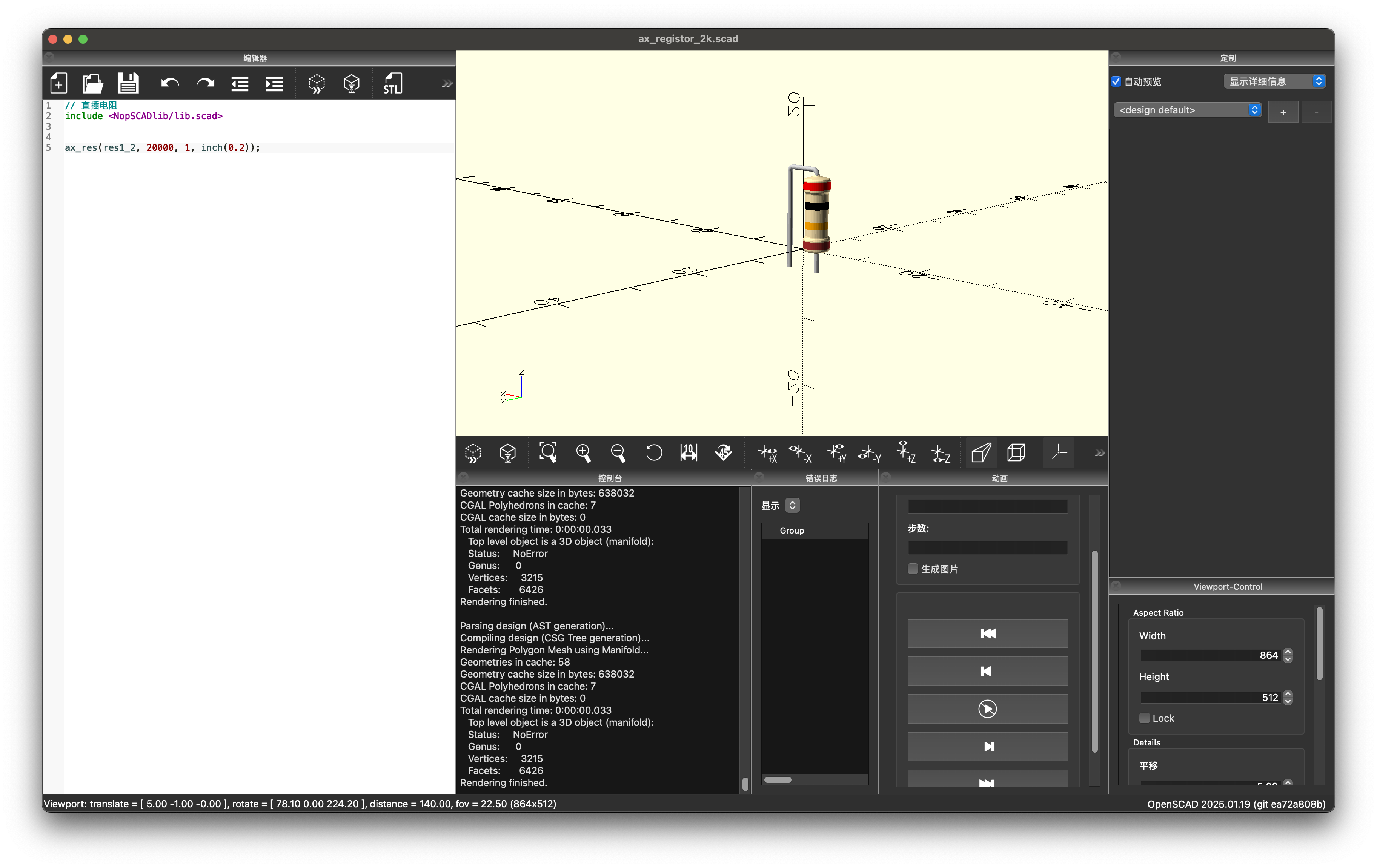
于是我们通过借助 NopSCADlib 绘制电阻的垂直封装,具体代码如下:
|
1 2 3 4 |
// 直插电阻 include <NopSCADlib/lib.scad> ax_res(res1_2, 20000, 1, inch(0.2)); |
渲染效果如下图:
问题现象
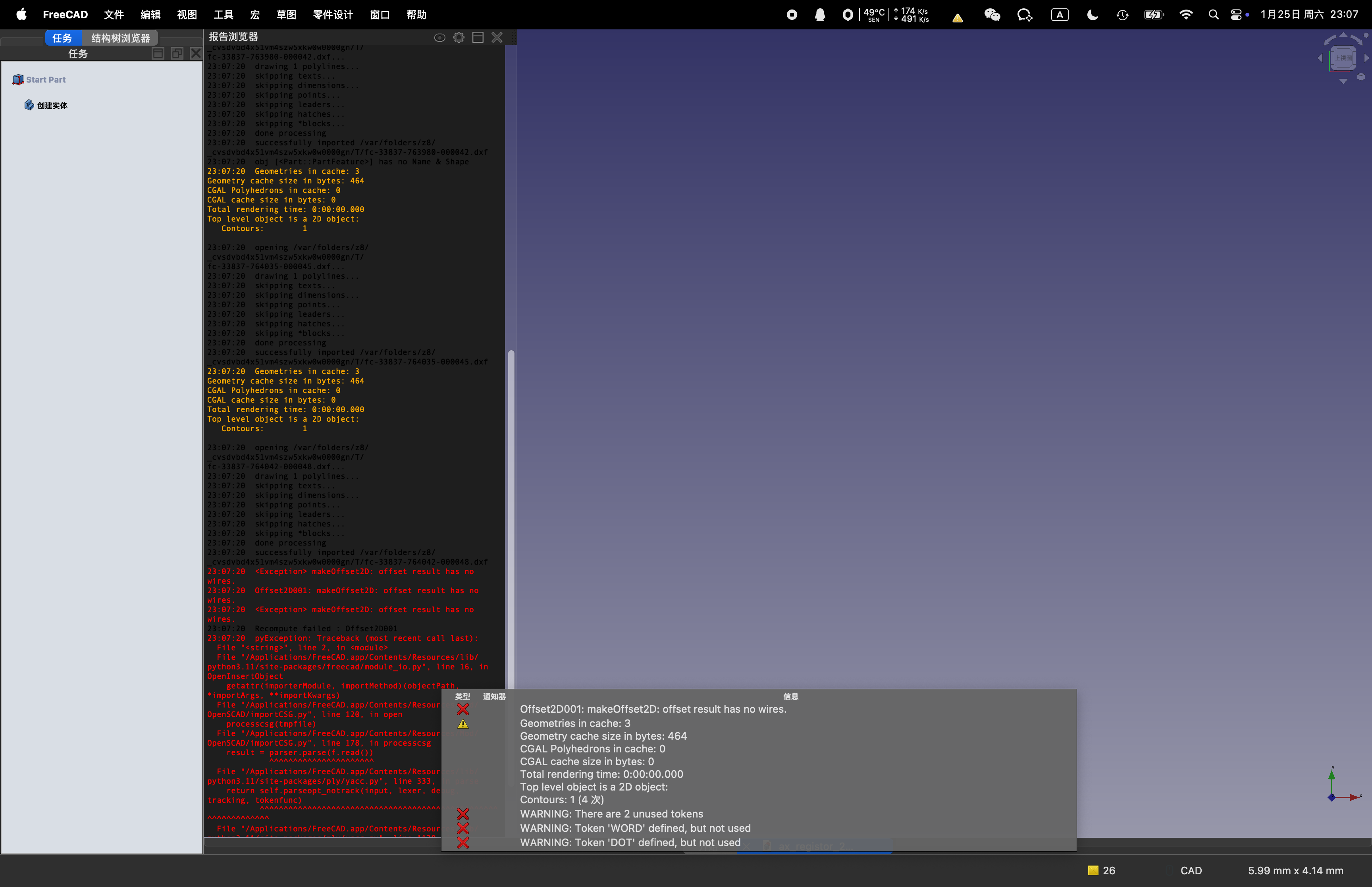
当我们使用 FreeCAD 导入这个模型的时候,会发生如下报错:
|
1 2 3 4 5 6 7 8 9 10 11 12 13 14 15 16 17 18 19 20 21 22 23 24 25 26 27 28 29 30 31 32 |
23:07:20 opening /var/folders/z8/_cvsdvbd4x51vm4szw5xkw0w0000gn/T/fc-33837-764042-000048.dxf... 23:07:20 drawing 1 polylines... 23:07:20 skipping texts... 23:07:20 skipping dimensions... 23:07:20 skipping points... 23:07:20 skipping leaders... 23:07:20 skipping hatches... 23:07:20 skipping *blocks... 23:07:20 done processing 23:07:20 successfully imported /var/folders/z8/_cvsdvbd4x51vm4szw5xkw0w0000gn/T/fc-33837-764042-000048.dxf 23:07:20 <Exception> makeOffset2D: offset result has no wires. 23:07:20 Offset2D001: makeOffset2D: offset result has no wires. 23:07:20 <Exception> makeOffset2D: offset result has no wires. 23:07:20 Recompute failed : Offset2D001 23:07:20 pyException: Traceback (most recent call last): File "<string>", line 2, in <module> File "/Applications/FreeCAD.app/Contents/Resources/lib/python3.11/site-packages/freecad/module_io.py", line 16, in OpenInsertObject getattr(importerModule, importMethod)(objectPath, *importArgs, **importKwargs) File "/Applications/FreeCAD.app/Contents/Resources/Mod/OpenSCAD/importCSG.py", line 120, in open processcsg(tmpfile) File "/Applications/FreeCAD.app/Contents/Resources/Mod/OpenSCAD/importCSG.py", line 178, in processcsg result = parser.parse(f.read()) ^^^^^^^^^^^^^^^^^^^^^^ File "/Applications/FreeCAD.app/Contents/Resources/lib/python3.11/site-packages/ply/yacc.py", line 333, in parse return self.parseopt_notrack(input, lexer, debug, tracking, tokenfunc) ^^^^^^^^^^^^^^^^^^^^^^^^^^^^^^^^^^^^^^^^^^^^^^^^^^^^^^^^^^^^^^^ File "/Applications/FreeCAD.app/Contents/Resources/lib/python3.11/site-packages/ply/yacc.py", line 1120, in parseopt_notrack p.callable(pslice) File "/Applications/FreeCAD.app/Contents/Resources/Mod/OpenSCAD/importCSG.py", line 457, in p_offset_action if subobj.Shape.Volume == 0 : ^^^^^^^^^^^^^^^^^^^ <class 'RuntimeError'>: shape is invalid |
具体如下图:
问题定位
我们尝试从 NopSCADlib 库中提取核心代码,观察到底是哪个函数引起的,分离后的代码如下:
|
1 2 3 4 5 6 7 8 9 10 11 12 13 14 15 16 17 18 19 20 21 22 23 24 25 26 27 28 29 30 31 32 33 34 35 36 37 38 39 40 41 42 43 44 45 46 47 48 49 50 51 52 53 54 55 56 57 58 59 60 61 62 63 64 65 66 67 68 69 70 71 72 73 74 75 76 77 78 79 80 81 82 83 84 85 86 87 88 89 90 91 92 93 94 95 96 97 98 99 100 101 102 103 104 105 106 107 108 109 110 111 112 113 114 115 116 117 118 119 120 121 122 123 124 125 126 127 128 129 130 131 132 133 134 135 136 137 138 139 140 141 142 143 144 145 146 147 148 149 150 151 152 153 154 155 156 157 158 159 160 161 162 163 164 165 166 167 168 169 170 171 172 173 174 175 176 177 178 179 180 181 182 183 184 185 186 187 188 189 190 191 192 193 194 195 196 197 198 199 200 201 202 203 204 205 |
// 直插电阻 // include <NopSCADlib/lib.scad> extrusion_width = is_undef($extrusion_width) ? 0.5 : $extrusion_width; // filament width when printing $fa = $fa == 12 ? 6 : $fa; // Defaults for printing //$fs = $fs == 2 ? extrusion_width / 2 : $fs; fa = is_undef($vitamin_fa) ? 6 : $vitamin_fa; // Used for drawing vitamins, rather than printing. fs = is_undef($vitamin_fs) ? 0.25 : $vitamin_fs; eps = 1/128; // small fudge factor to stop CSG barfing on coincident faces. fn = 32; function inch(x) = x * 25.4; function sqr(x) = x * x; //! Returns the square of `x` module translate_z(z) //! Shortcut for Z only translations translate([0, 0, z]) children(); module vflip(flip=true) //! Invert children by doing a 180° flip around the X axis rotate([flip ? 180 : 0, 0, 0]) children(); module solder_meniscus(ir = 0.3, r = 1, h = 0.7) { //! Draw a solder meniscus $fn = fn; color("silver") rotate_extrude() difference() { square([r, h]); translate([r + eps, h + eps]) ellipse(r - ir + eps, h); } } module solder(ir = 0.3) { //! Maybe add solder meniscus if $solder is set if(!is_undef($solder)) vflip() translate_z($solder.z) solder_meniscus(ir = ir, r = $solder.x); } module wire_link(d, l, h = 1, tail = 3, sleeve = false) { //! Draw a wire jumper link. `sleeve` can be a list with the diameter and colour. If `l` is zero then a vertical wire is drawn. // vitamin(str("wire_link(", d, ", ", l, arg(h, 1, "h"), arg(tail, 3, "tail"), arg(sleeve, false, "sleeve"), // "): Wire link ", d, "mm x ", l ? str(l / inch(1), "\"") : str(h + tail,"mm"), sleeve ? str(" with ", sleeve[1], " sleeving") : "")); r = d; $fn = fn; color("silver") if(l) { for(side = [-1, 1]) { translate([side * l / 2, 0, -tail]) cylinder(d = d, h = tail + h - r); translate([side * (l / 2 - r), 0, h - r]) rotate([90, 0, side * 90 - 90]) rotate_extrude(angle = 90, $fn = fn * 2) translate([r, 0]) circle(d = d, $fn = fn); translate([side * l /2, 0]) if(tail > 1) solder(ir = d / 2); else if(!is_undef($solder)) translate_z(0.1) solder_meniscus(ir = d / 2, r = $solder.x, h = h - r - 0.1); } translate_z(h) rotate([0, -90, 0]) cylinder(d = d, h = l - 2 * r, center = true); } else { translate_z(-tail) cylinder(d = d, h = tail + h); solder(ir = d / 2); } if(sleeve) color(sleeve[1]) translate_z(h) rotate([0, 90, 0]) cylinder(d = sleeve[0], h = l - 2 * r, center = true); } module round(r, ir = undef, or = undef) { //! Round a 2D child, single radius or separate inside and outside radii IR = is_undef(ir) ? r : ir; OR = is_undef(or) ? r : or; offset(OR) offset(-OR -IR) offset(IR) children(); } module not_on_bom(on = false) //! Specify the following child parts are not on the BOM, for example when they are on a PCB that comes assembled let($on_bom = on) children(); function ax_res_wattage(type) = type[1]; //! Power rating function ax_res_length(type) = type[2]; //! Body length function ax_res_diameter(type)= type[3]; //! Body diameter function ax_res_end_d(type) = type[4]; //! End cap diameter function ax_res_end_l(type) = type[5]; //! End cap length function ax_res_wire(type) = type[6]; //! Wire diameter function ax_res_colour(type) = type[7]; //! Body colour module orientate_axial(length, height, pitch, wire_d) { // Orient horizontal or vertical and add the wires min_pitch = ceil((length + 1) / inch(0.1)) * inch(0.1); lead_pitch = pitch ? pitch : min_pitch; if(lead_pitch > min_pitch - eps) { not_on_bom() wire_link(wire_d, lead_pitch, height); translate_z(height) rotate([0, 90, 0]) children(); } else { not_on_bom() wire_link(wire_d, lead_pitch, length + 0.7 + wire_d); translate([-pitch / 2, 0, length / 2 + 0.2]) children(); } } module ax_res(type, value, tol = 5, pitch = 0) { //! Through hole axial resistor. If `pitch` is zero the minimum is used. If below the minimum the resistor is placed vertical. // vitamin(str("ax_res(", type[0], ", ", value, arg(tol, 5, "tol"), "): Resistor ", value, " Ohms ", tol, "% ",ax_res_wattage(type), "W")); wire_d = ax_res_wire(type); end_d = ax_res_end_d(type); end_l = ax_res_end_l(type); body_d = ax_res_diameter(type); length = ax_res_length(type); h = end_d / 2; r = 0.3; colours = ["gold", "silver", "black", "brown", "red", "orange", "yellow", "green", "blue", "violet", "grey", "white"]; $fs = fs; $fa = fa; exp = floor(log(value) + eps); mult = exp - (len(str(value / pow(10, exp - 1))) > 2 ? 2 : 1); digits = str(value / pow(10, mult)); bands = [ for(d = digits) colours[ord(d) - ord("0") + 2], colours[mult + 2], tol == 1 ? "brown" : tol == 2 ? "red" : tol == 5 ? "gold" : tol == 10 ? "silver" : "error" ]; module profile(o = 0) intersection() { offset(o) round(r) union(){ translate([0, -length / 2]) square([body_d / 2, length]); for(end = [-1, 1]) hull() { translate([0, end * (length - end_l) / 2 - end_l / 2]) square([end_d / 2, end_l]); translate([0, end * length / 2]) square([wire_d, 2 * r], center = true); } translate([-5, 0]) square([10 + wire_d, length + 4 * r], center = true); } translate([0, -50]) square([50, 100]); } orientate_axial(length, h, pitch, wire_d) { color(ax_res_colour(type)) rotate_extrude() profile(); for(i = [0 : len(bands) - 1]) color(bands[i]) rotate_extrude() intersection() { profile(eps); translate([0, length / 2 - end_l / 2 - i * (length - end_l) / (len(bands) - 1)]) square([end_d + 1, (length - end_l) / len(bands) / 2], center = true); } } } //vitamins/axials.scad // res1_8 = ["res1_8", 0.125, 3.3, 1.35, 1.7, 1, 0.33, "#FAE3AC"]; // res1_4 = ["res1_4", 0.25, 5.7, 1.85, 2.3, 1.5, 0.55, "#FAE3AC"]; res1_2 = ["res1_2", 0.5, 10, 3.25, 3.7, 1.8, 0.70, "#FAE3AC"]; // ax_resistors = [res1_8, res1_4, res1_2]; ax_res(res1_2, 20000, 1, inch(0.2)); |
经过反复的注释代码,发现这个报错是由于 round 函数引起的,如下:
|
1 2 3 4 5 6 7 8 |
module round(r, ir = undef, or = undef) { //! Round a 2D child, single radius or separate inside and outside radii IR = is_undef(ir) ? r : ir; OR = is_undef(or) ? r : or; offset(OR) offset(-OR -IR) offset(IR) children(); } |
最终定位到 offset 函数。
问题原因
这个问题的原因是因为 FreeCAD 对于 OpenSCAD 的 offset 命令支持上存在问题导致的。
解决过程
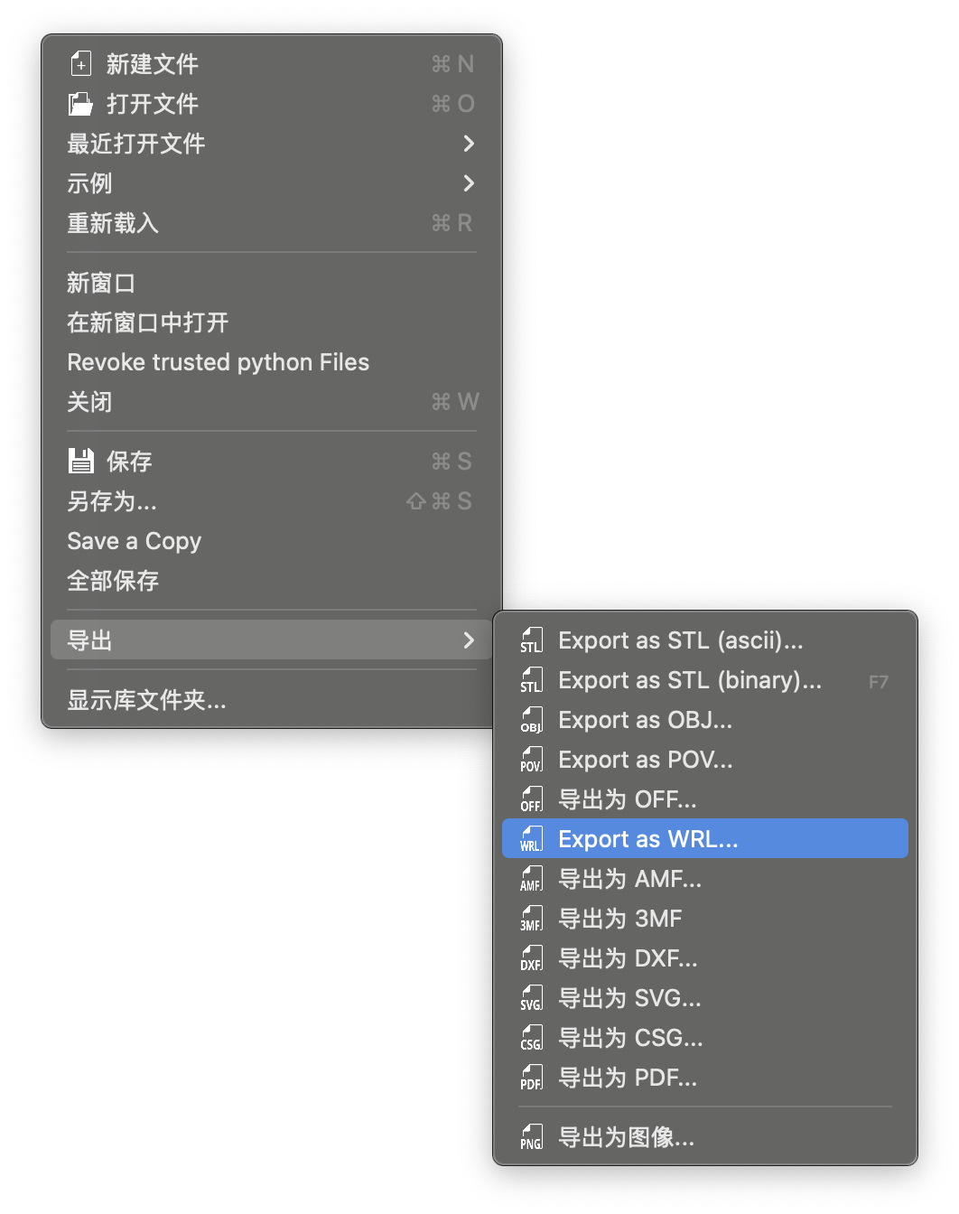
需要注意的是,KiCAD 支持 WRL、STP 两种格式的 3D 模型文件,但是 OpenSCAD 目前版本只支持 WRL 格式的导出。
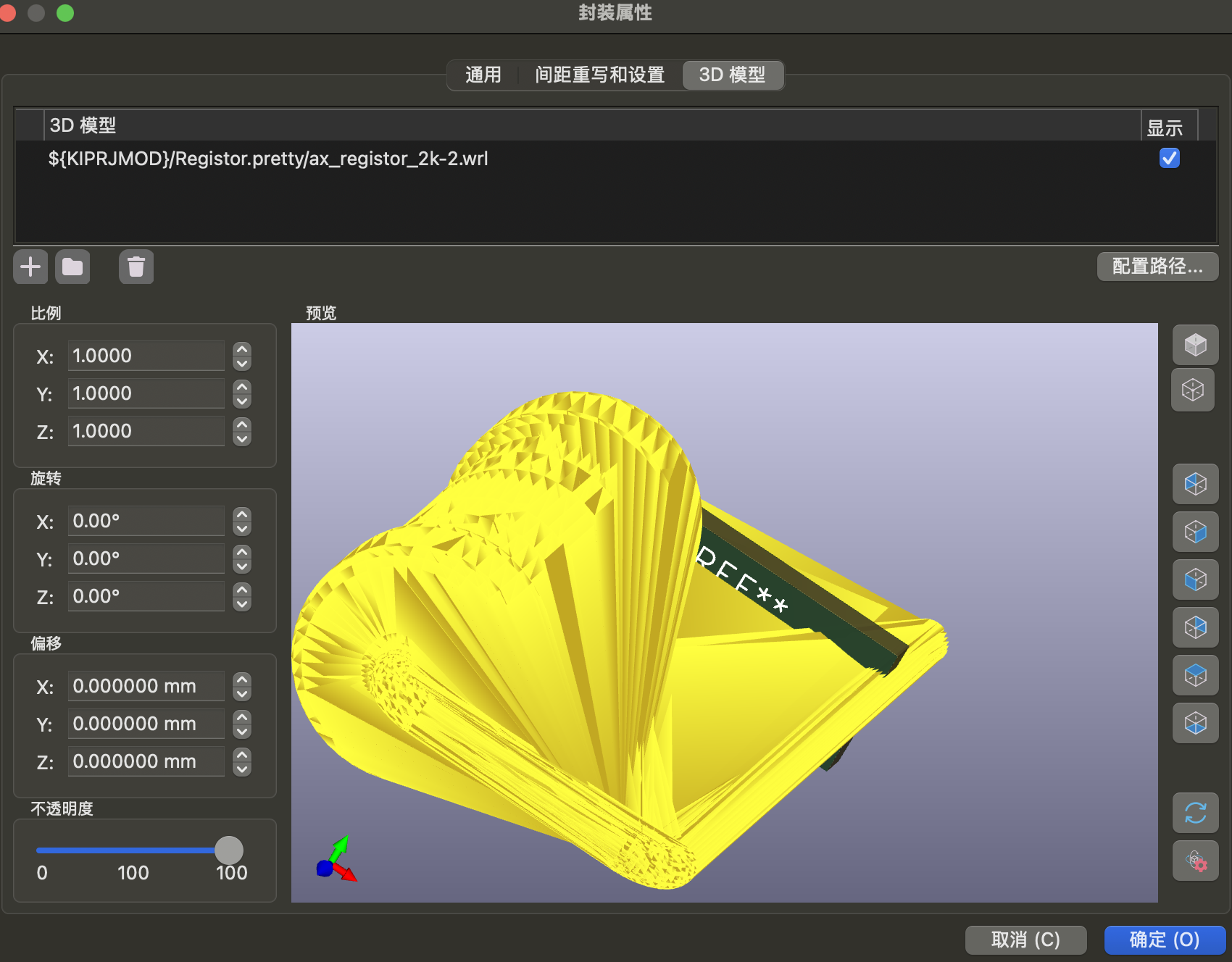
那么为什么不直接使用 OpenSCAD 导出的 WRL 格式的模型文件呢?
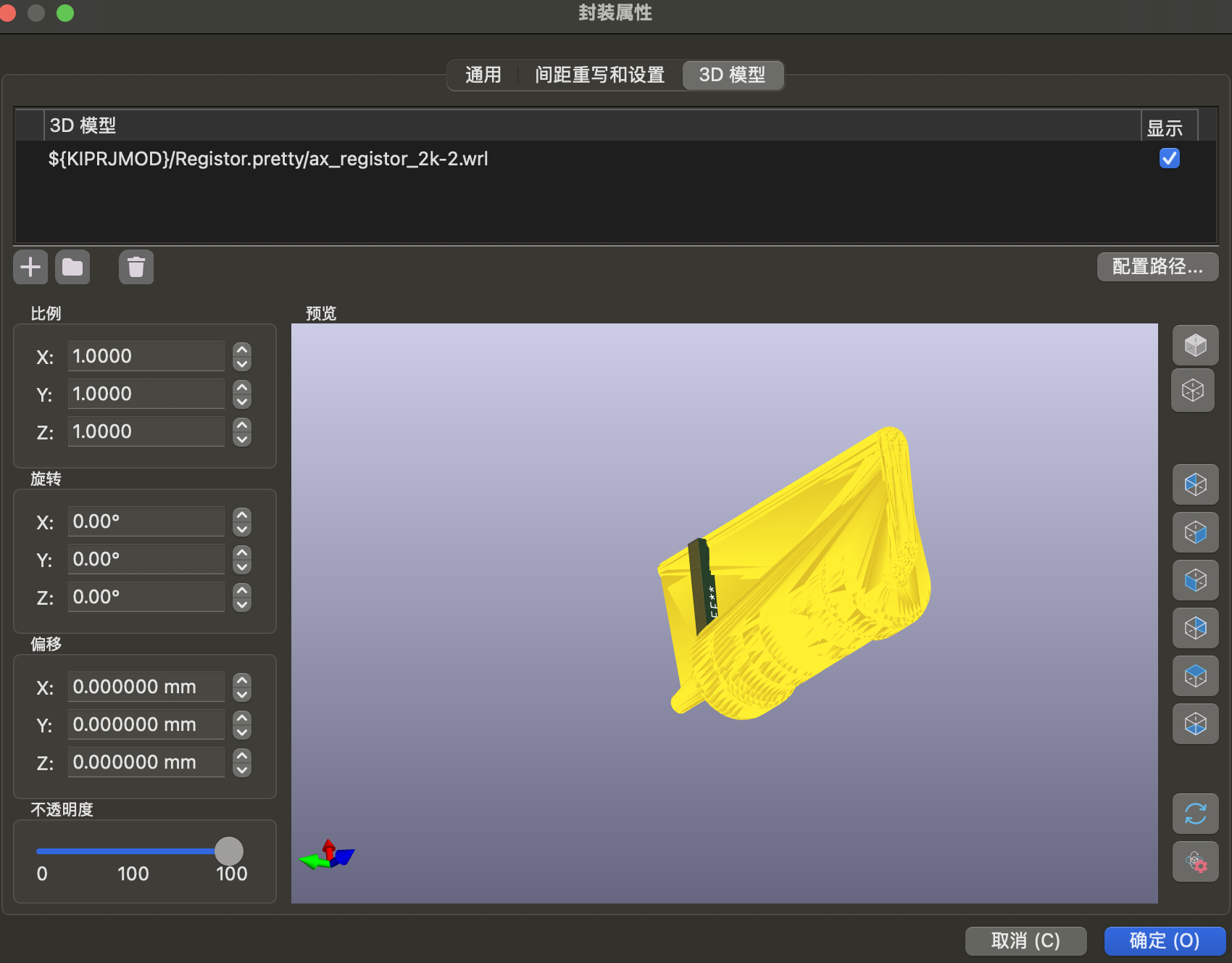
答案就是,导出的模型文件不正确,实际效果如下图:
方案尝试
我们希望达到的效果是,模型显示正常,并且可以保留模型颜色。
-
从 OpenSCAD 自身开始入手,是否有办法让 OpenSCAD 直接导出 STP 格式呢?答案是存在的,那就是 PythonSCAD 这个项目支持直接导出 STP 格式。可惜的是,导出的模型 KiCAD 完全无法正常加载。
-
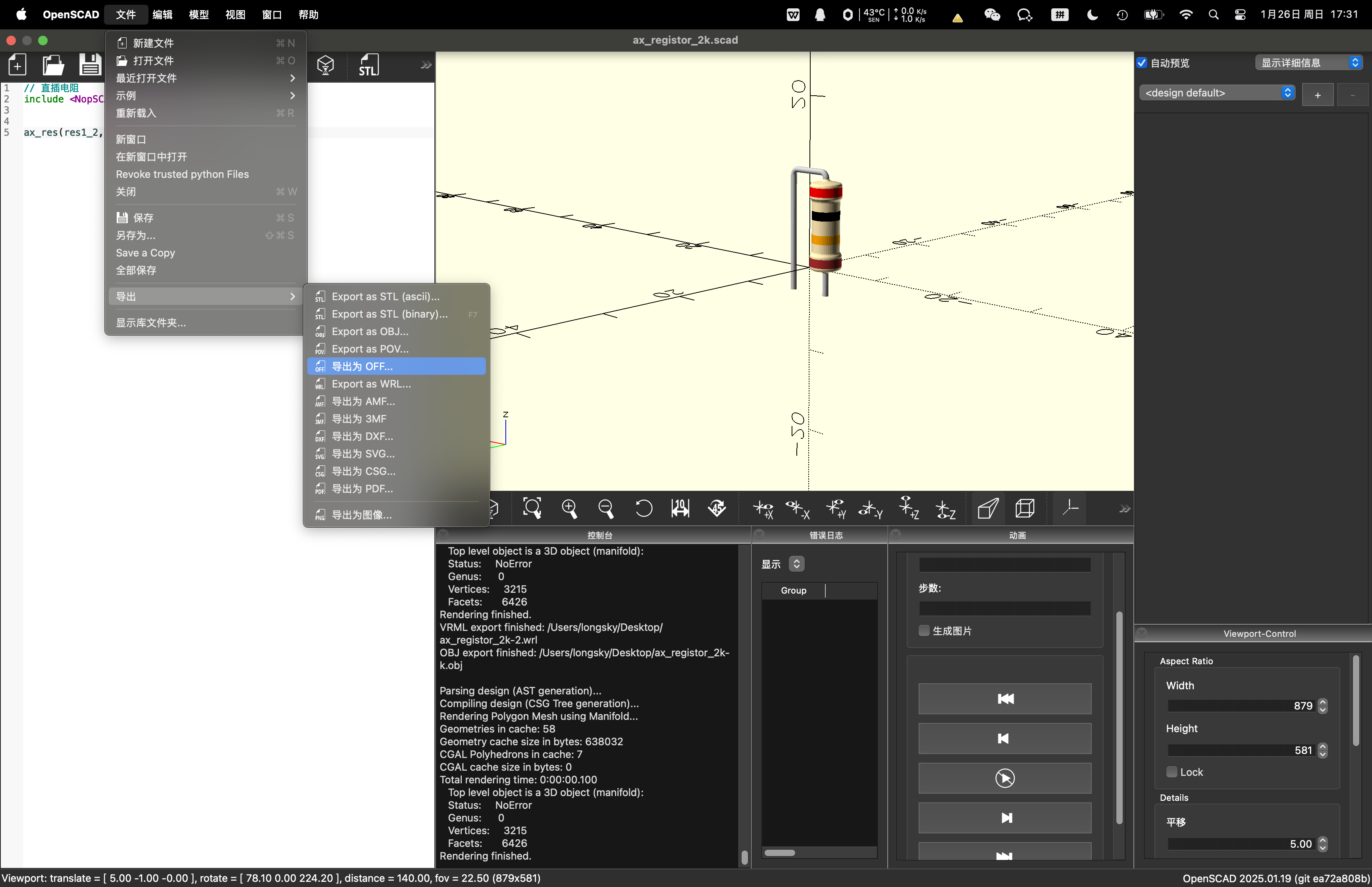
从 OpenSCAD 导出其他能保留颜色的3D格式,然后进行模型转换。目前可以支持颜色的格式有 3MF、OBJ、OFF、WRL 这几种格式,我们需要进行格式转换成 STP / WRL 格式,另外 KiCAD 要求导出的 STP 格式使用毫米为单位,WRL 格式使用一个 WRL尺寸单位对应 0.1 英寸进行换算。目前测试发现 OpenSCAD 导出 3MF、OFF格式的时候是会携带颜色信息的,其他格式都没有颜色信息。
确定方案之后,我们开始进行尝试,首先是通过在线工具进行转换,通过尝试,发现 ImageToStl 网站的转换是非常完美的,通过 3MF、OFF 进行格式转换成 STP 格式之后,可以完美的保留颜色,美中不足的是国内访问可能会很慢。
国内的 迪威模型 进行转换的时候,无法正常的保留颜色,如果对于颜色不看重的情况下,是个备选项。
使用 FreeCAD 进行模型转换的时候 1.0.0 版本会直接卡死,weekly build 版本会丢失颜色信息。
也可以使用开源项目 assimp 进行转换,转换后丢失颜色信息:
|
1 2 3 |
$ brew install assimp $ assimp export xx.3mf xx.stp --format=step |
最终方案
目前尝试的比较好的解决方法如下:
- 通过 OpenSCAD 导出 OFF 格式的 3D 模型(目的是保留颜色信息);
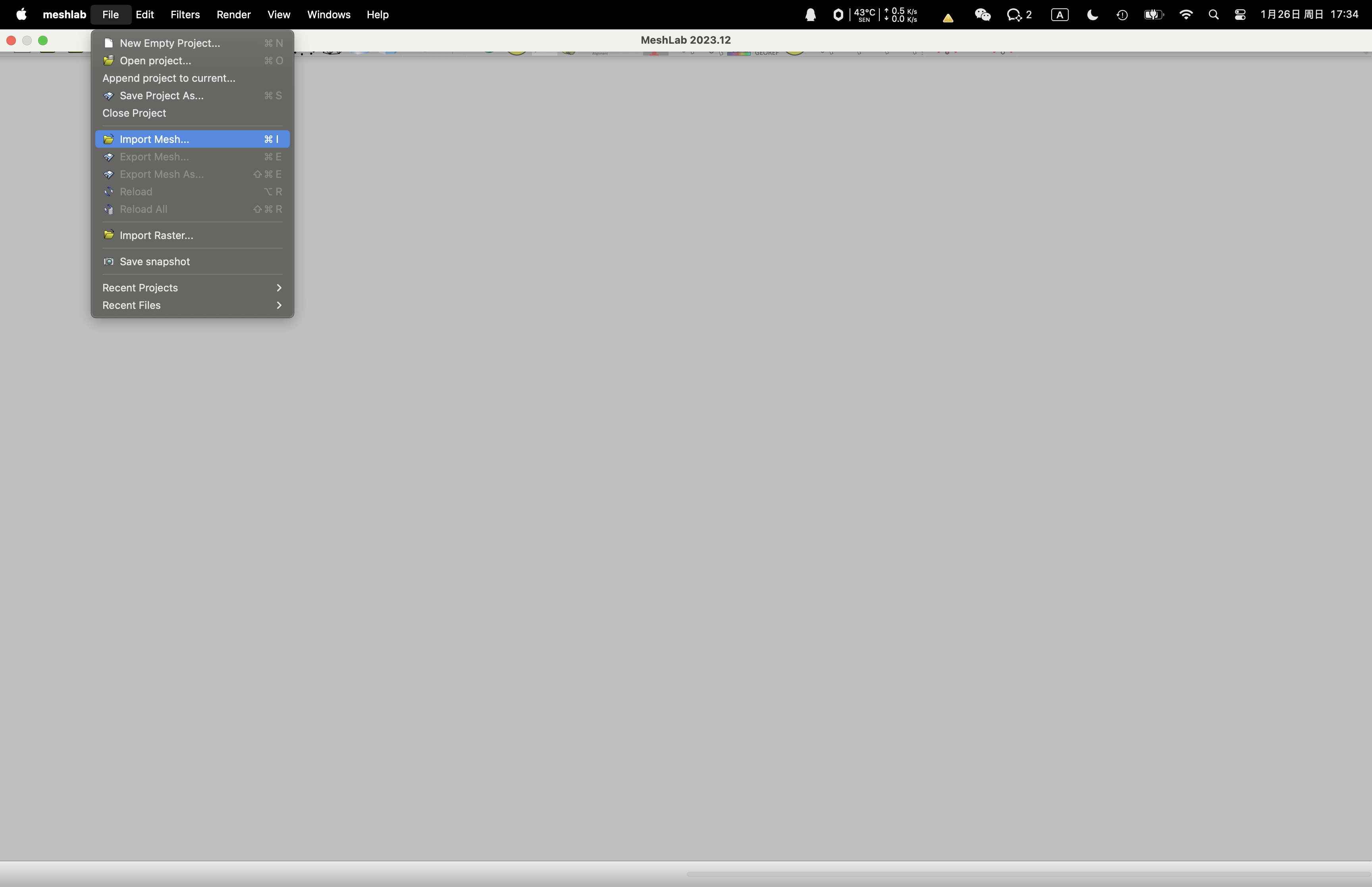
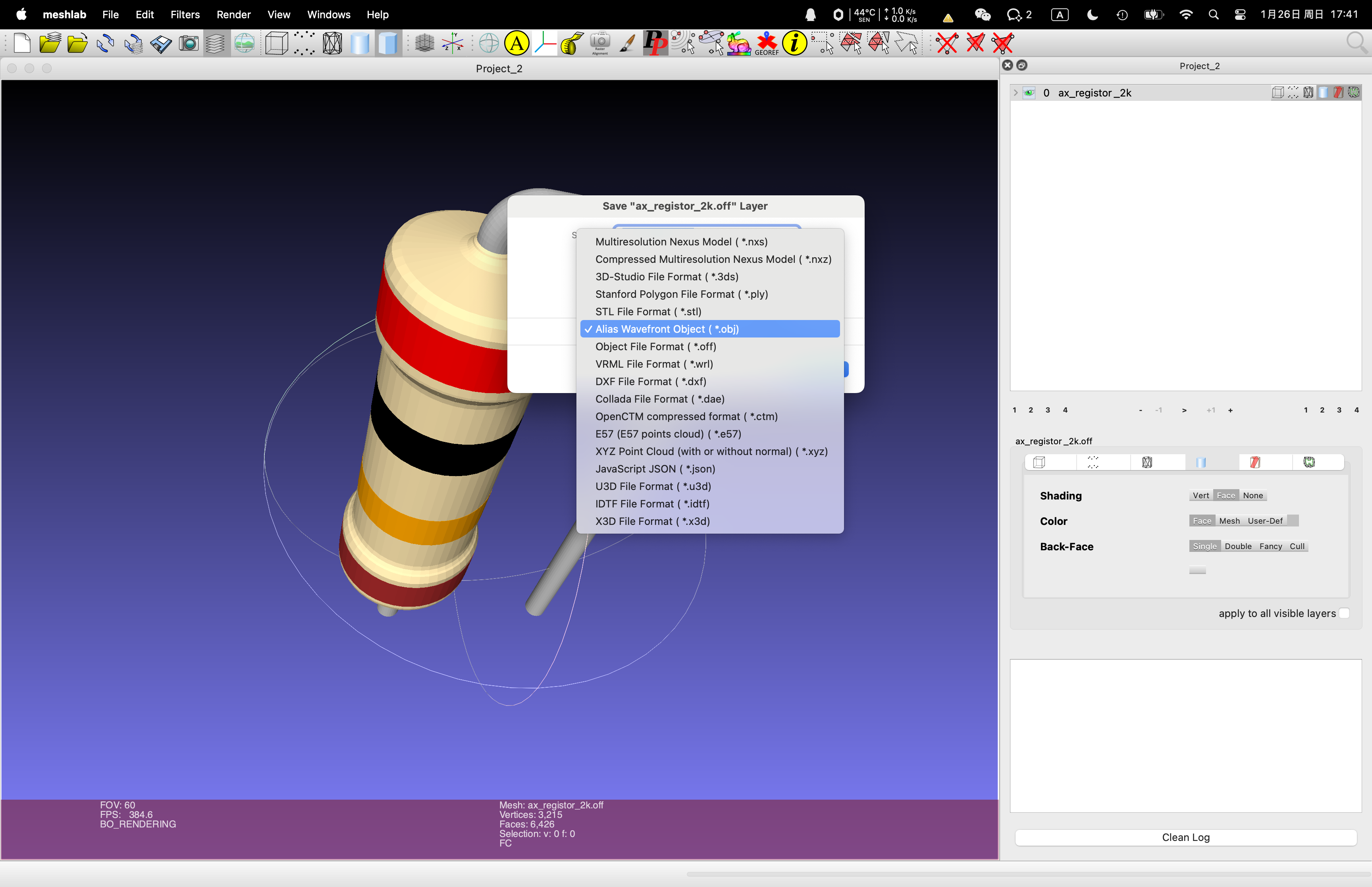
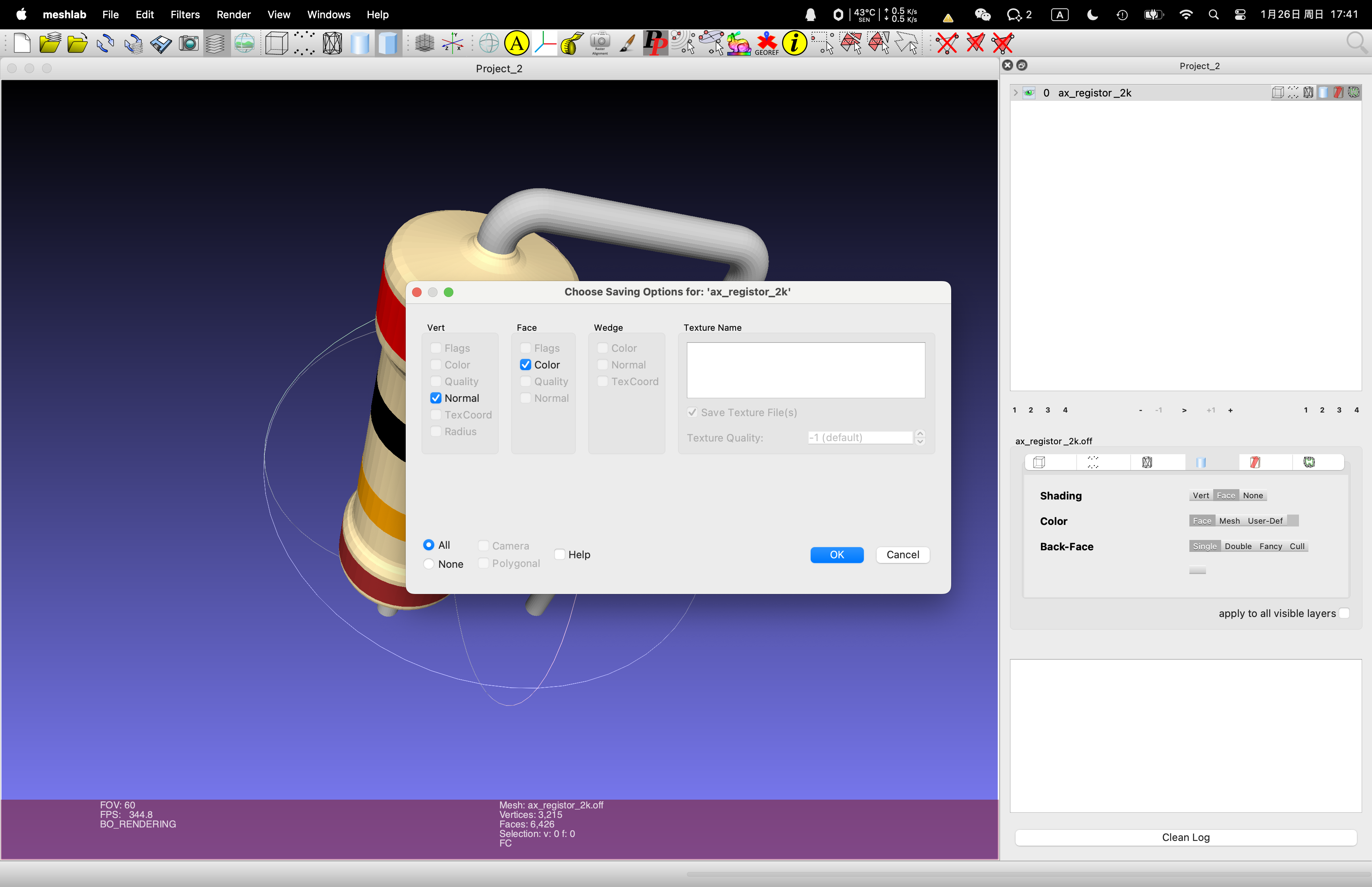
- 通过 MeshLab 转换成 OBJ 格式的 3D 模型,同样是为了保留颜色信息;
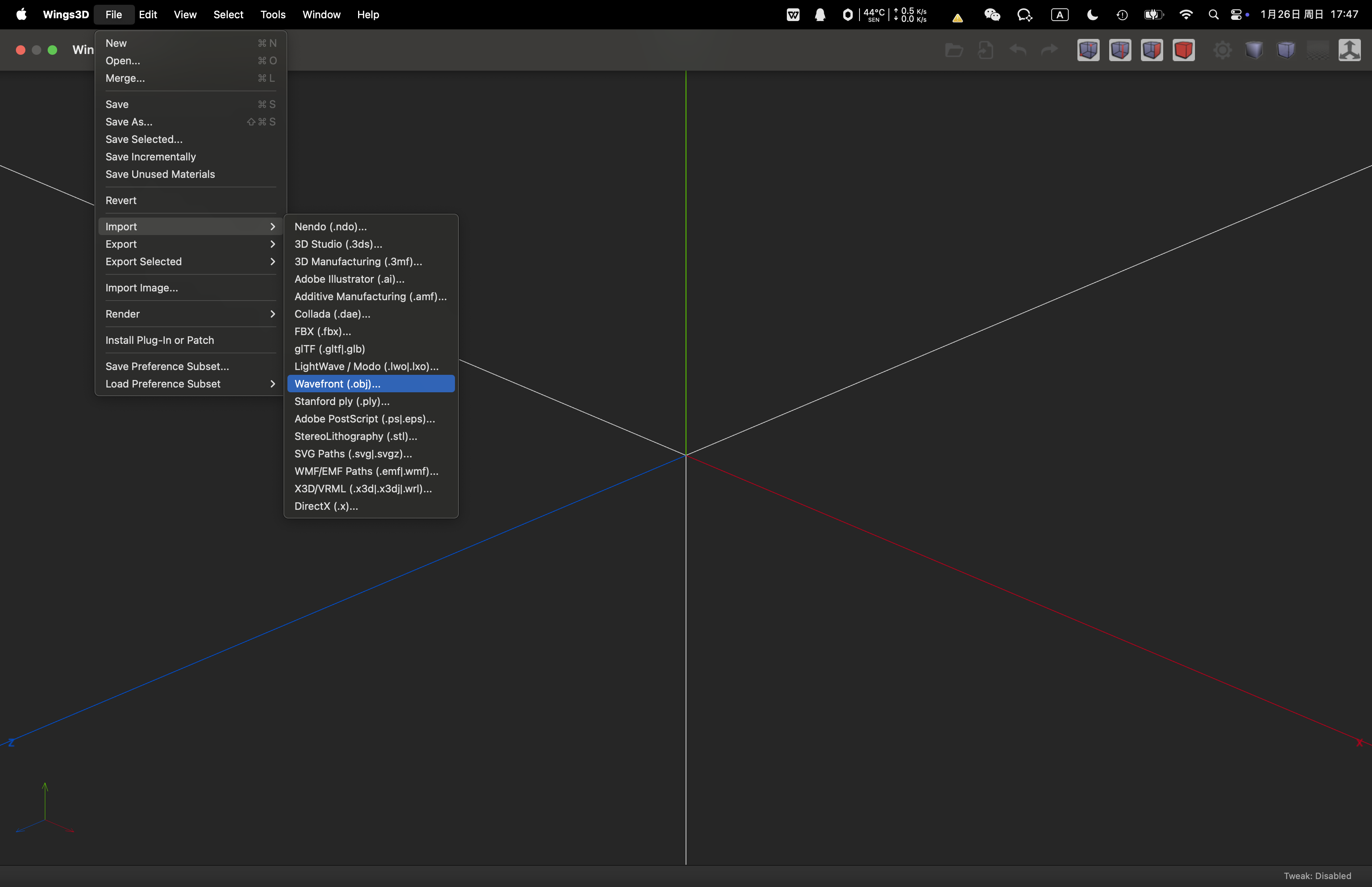
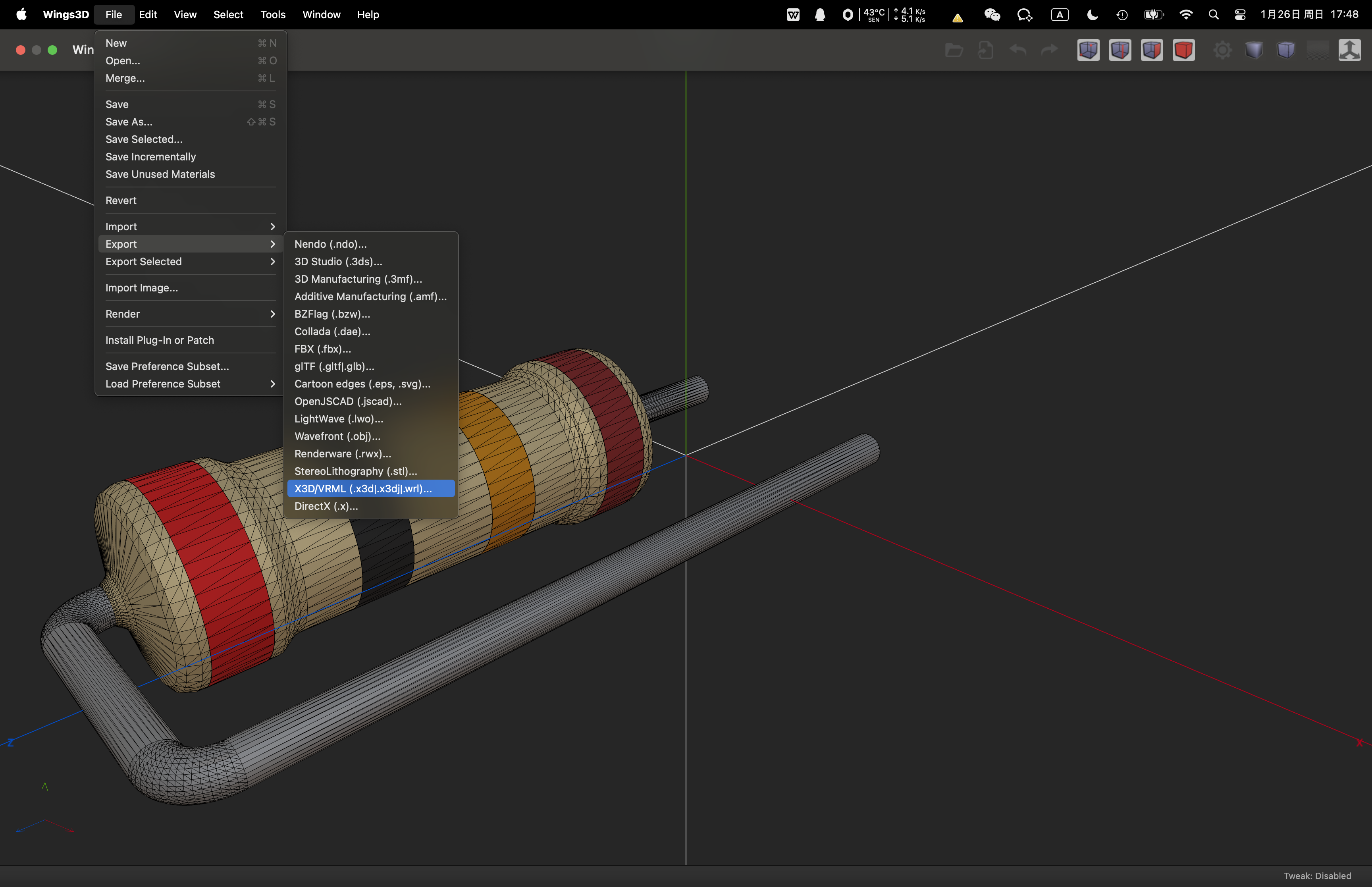
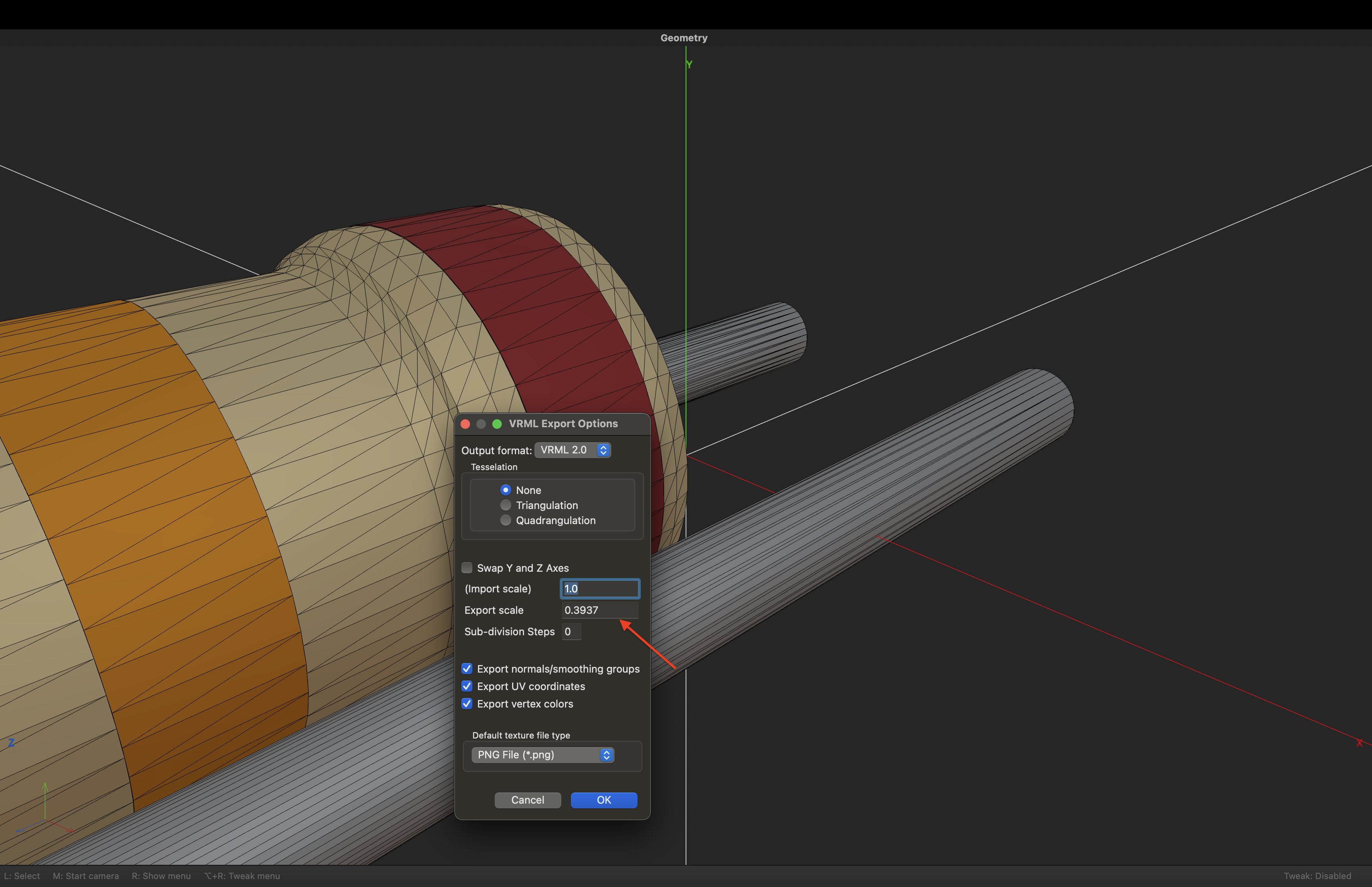
- 通过 Wings 3D 转换 OBJ 格式的 3D 模型为 WRL 格式;
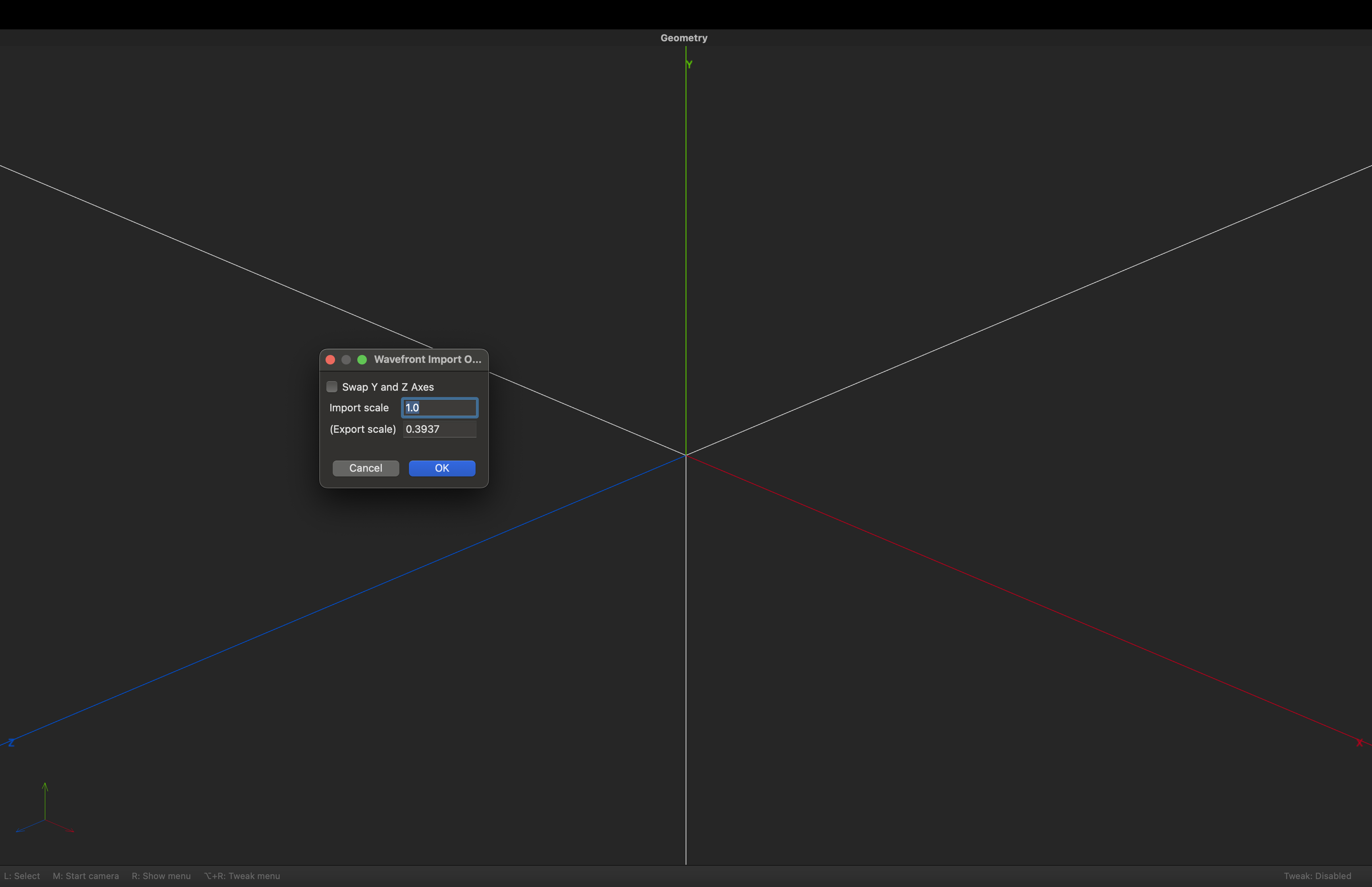
注意: 下图中的 Export scale 中的 0.3937 这个数值的来源, KiCAD 要求 WRL 格式使用英寸作为长度单位,并且要求一个 WRL尺寸单位对应 0.1 英寸进行换算。 而 OpenSCAD 模型的默认单位是毫米,因此此处需要进行单位换算。 0.1 in = 2.54mm,所以缩放比例为 1 / 2.54 = 0.3937
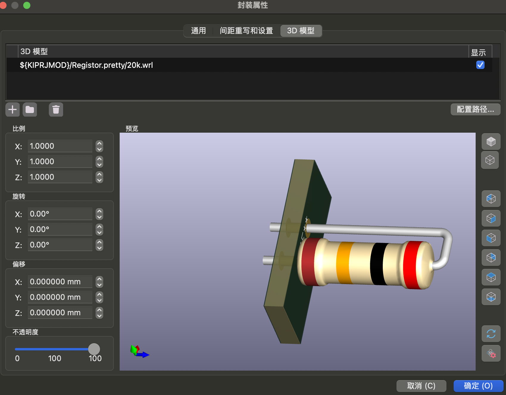
- 使用 KiCAD 加载 WRL 格式的模型。
注意: 如果导入文件发现色彩丢失,出现如下图的情况:
可以检查一下文件名,如果文件名为类似 R_Axial_L6.5mm_D2.3mm_P7.62mm_100Ω_Horizontal 的情况,则会出现上图的现象。
这个问题的原因是由于文件名中的特殊字符导致 Wings3D 内部解析异常,改名成 R_Axial_L6.5mm_D2.3mm_P7.62mm_100_Horizontal,重复上述操作(需要从 OpenSCAD 开始修正文件名)即可解决此问题。
注意文件名中的 Ω 。
参考连接
- Open Asset Import Library (assimp)
- 三维模型格式转换神器-assimp
- Exported STEP files do not include the colours #452
- assimp/doc/Fileformats.md
- lib3mf is a C++ implementation of the 3D Manufacturing Format file standard.
- 使用Assimp实现gltf到obj的转换
- Assimp dep for import / export of glTF, Collada, STEP, PLY, X3D #5180
- OpenSCAD Export color information #4671
- ColorSCAD
- OpenSCAD color(), material() and part() [$325] #1608
- 3MF Compatibility Matrix
- Color support in 3D rendering (includes OFF color import / export, green subtracted faces) #5185
- FreeCAD 3MF: 3D Manufacturing Format
- Wrl scaling question
